
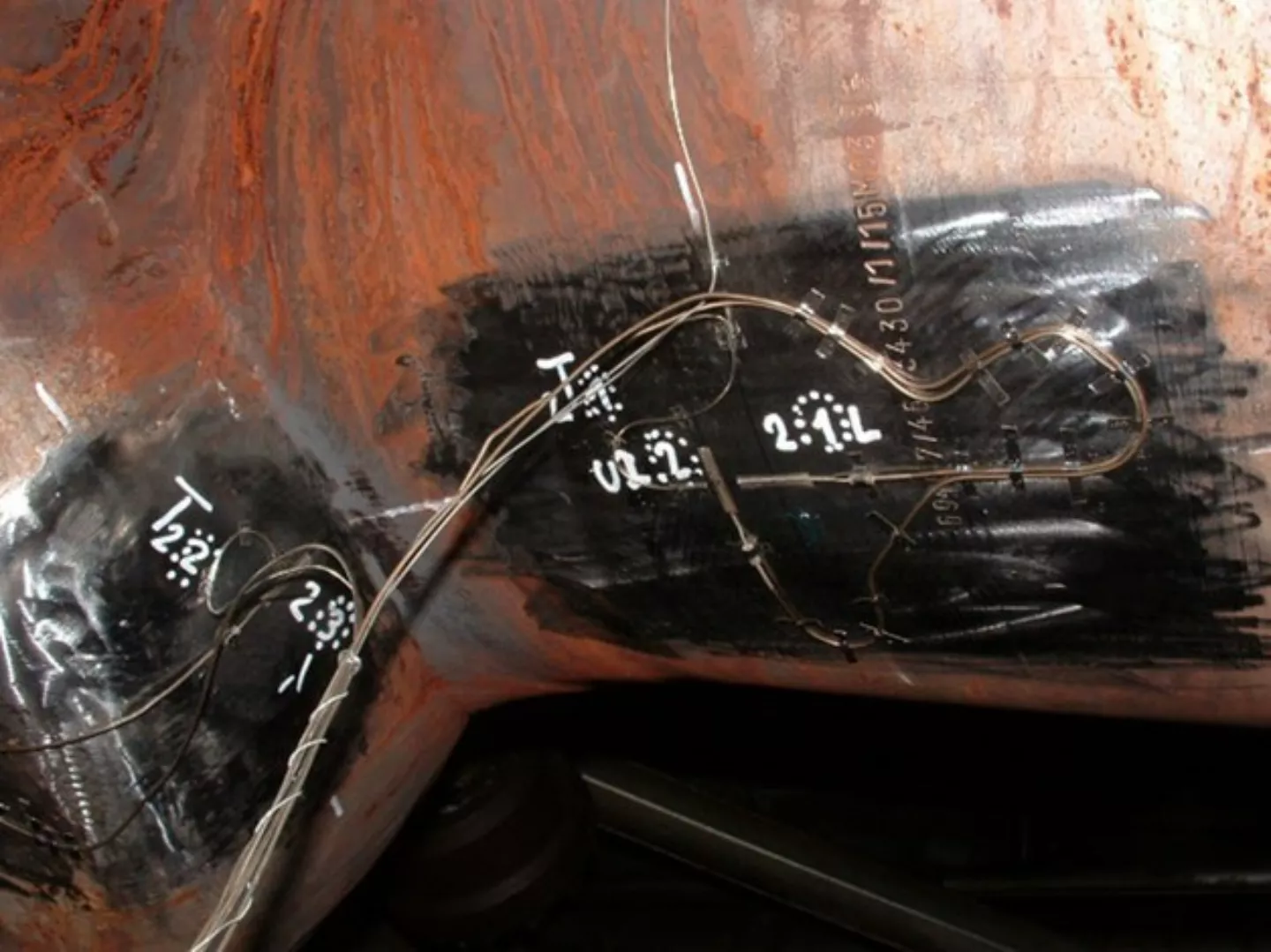

The choice of the appropriate strain gauge geometry depends on which strain directions need to be measured and whether these directions are already known. This article explains the most important strain gauge configurations – from linear strain gauges and T-rosettes to three-element rosettes and special geometries for torsion, strain distributions and full-bridge circuits.
Which strain gauge geometry is suitable for which measurement task?
Strain gauges measure strain along the axis of their measuring grid. The appropriate strain gauge geometry therefore primarily depends on how many strain directions need to be measured and whether the principal strain directions at the measuring point are already known.
For a known uniaxial strain direction, a linear strain gauge is usually sufficient. If two mutually perpendicular directions need to be measured, a T-rosette is suitable. If the magnitude and direction of the principal strains are unknown, three-element rosettes are used. In addition, special strain gauge geometries are available for torsion, bending, strain gradients and complete bridge circuits.
The selection of the appropriate configuration depends on the measurement task, component geometry, material, environmental conditions and the required measurand. It is also important to determine whether local strains, strain distributions or stresses calculated from the measured values are to be determined.
For measurements under changing temperatures, it must also be checked whether the strain gauge is matched to the thermal expansion characteristics of the component material. The article Temperature Compensation for strain gauges explains how self-temperature-compensated strain gauges are selected and which additional compensation methods are available.
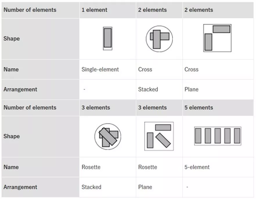
Selecting the appropriate strain gauge geometry
Before selecting a strain gauge, it should be determined what strain state is expected at the measuring point. Indications can be obtained from analytical calculations, FEM simulations, empirical data or preliminary tests. The subsequent measurement is often used to verify these assumptions and adjust them if necessary. The key question is whether the principal strain direction is known. If it is, a linear strain gauge or T-rosette may be sufficient. If the direction is unknown or a complex plane strain state exists, a three-element rosette is required.
In addition to geometry, other criteria must be taken into account. These include the available measuring area, measuring grid length, nominal resistance, temperature range, component material and type of loading. For dynamic measurements, fatigue resistance, the connection method and the quality of the strain gauge installation also play an important role.
Linear strain gauges
A linear strain gauge has a single measuring grid and measures strain along its longitudinal axis. It is suitable for measurement tasks in which the principal strain direction is known and the strain state is essentially uniaxial.
Typical applications include tensile tests, compression tests and local strain measurements on components with a known load path. A linear strain gauge can also be useful for component modifications or comparative measurements when critical locations and load directions are already known. To measure the maximum strain correctly, the strain gauge must be aligned as accurately as possible with the direction of strain. If the measuring grid axis deviates from the actual principal strain direction, a measurement error occurs. A linear strain gauge is therefore not suitable when the strain direction is unknown or varies significantly.
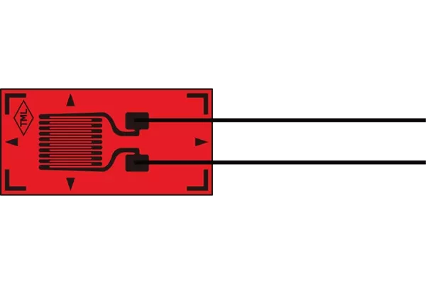
The measuring grid length should be matched to the measurement task.
- Short measuring grids are suitable for small measuring points and local strain gradients.
- Longer measuring grids average the strain over a larger area and are advantageous, for example, for concrete, composite materials or inhomogeneous materials.
T-rosette
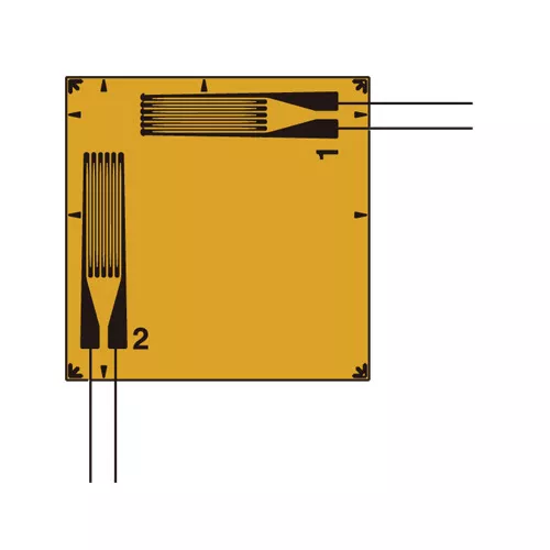
A T-rosette consists of two measuring grids arranged perpendicular to each other, typically in the 0° and 90° directions. It is used when two relevant strain directions are known or when longitudinal and transverse strain need to be measured simultaneously.
A typical application is a tensile test. One measuring grid measures the strain in the loading direction, while the second measures the transverse strain. Under suitable conditions, this also allows transverse contraction and the Poisson’s ratio to be determined. T-rosettes are also suitable for biaxial strain states when the principal directions are already known. The prerequisite is that the rosette is correctly aligned with these directions. If the principal directions are unknown, a T-rosette is not sufficient. In this case, a three-element rosette is required.
Shear and torsion strain gauges
For torsion and shear measurements, strain gauge geometries are used in which the measuring grids are typically arranged at +45° and −45° relative to the reference axis. On a shaft subjected to torsion, the maximum strains occur in these directions. By appropriately arranging and connecting the strain gauges, torsional signals can be measured selectively while other load components, such as bending or tension, can be partially compensated.
Shear and torsion strain gauges are used, among other applications, for torque measurements on shafts, test setups and custom torque transducers.
Three-element rosettes
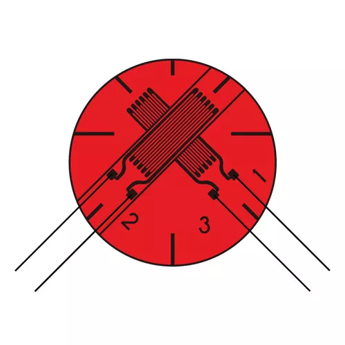
If the principal strain directions at the measuring point are unknown, three strains are measured in different directions. From these three measured values, the maximum and minimum principal strains and their orientation can be calculated.
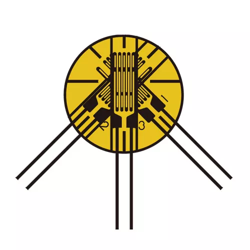
A three-element rosette does not measure an arbitrary three-dimensional stress state. It is generally used to investigate a plane strain state at the surface of a component.
Each measuring grid measures the normal strain along its own axis. The measured values are then evaluated using strain transformation equations or corresponding rosette equations. The measuring grids do not compensate one another; instead, together they provide the information required for the calculation.
Rectangular rosette
The rectangular rosette has three measuring grids oriented at 0°, 45° and 90°. It is one of the most commonly used rosette configurations for experimental stress analysis.
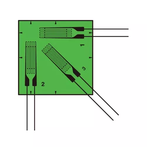
The principal strains, principal strain direction and maximum shear strain can be determined from the three measured directional strains. If the material properties are known and an appropriate material model is used, the principal stresses can also be calculated.
The rectangular rosette is particularly suitable when little is known about the strain direction at the measuring point.
Delta rosette
The delta rosette has three measuring grids oriented at 0°, 60° and 120°. In principle, it serves the same purpose as a rectangular rosette: determining unknown principal strains and their directions.
Which of the two rosette configurations is more suitable depends, among other factors, on the available measuring area, lead routing, the strain gradient and the requirements for data evaluation.
Planar and stacked rosettes
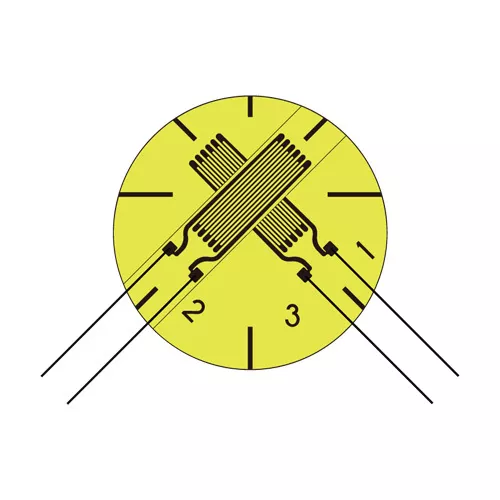
Rosettes are available in planar and stacked configurations. In a planar rosette, the measuring grids are positioned next to one another in the same plane. The design is comparatively flat and heat dissipation is generally favorable. However, the individual grids do not measure at exactly the same geometric point.
In a stacked rosette, the measuring grids are positioned on top of one another. As a result, all directions are measured at almost the same point. This is particularly advantageous when strong local strain gradients occur. However, the design is thicker and may exhibit greater self-heating.
The choice between the two configurations therefore depends on the size of the measuring point, the expected strain gradient and the thermal boundary conditions.
Double linear strain gauges
Double linear strain gauges have two parallel measuring grids on a common carrier. They are used when strains at two closely spaced positions need to be compared or local strain differences need to be measured. Typical applications include bending investigations, measuring strain gradients or comparing two measuring points where installation space is limited.
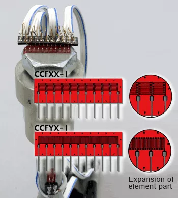
Strain gauge chains
Strain gauge chains consist of several measuring grids arranged at defined intervals on a common carrier. They enable the measurement of a strain distribution along a line.
These configurations are particularly suitable for areas with strong local variations, such as notches, cracks, weld seams or geometric transitions. Strain gauge chains are also useful for investigating stress concentrations.
Full-bridge strain gauges
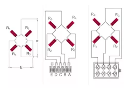
Full-bridge strain gauges contain four measuring grids that are already arranged for a complete Wheatstone bridge circuit. Depending on the geometry, they can be designed for bending, tension, compression or torsion.
They are frequently used in transducer manufacturing, for example in force, weighing or torque transducers. The coordinated arrangement of the four measuring grids can provide high sensitivity and effective compensation of unwanted influences.
Relationship between strain and stress
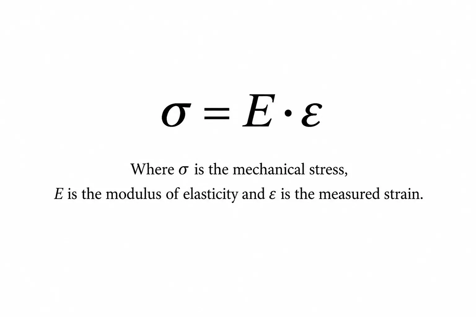
A strain gauge initially measures strain. Mechanical stresses are calculated only from the strain values and the material properties. In a biaxial stress state, Poisson’s ratio, the principal strains and assumptions about the material behavior must also be taken into account. A rosette therefore does not directly provide the principal stresses. These are calculated from the measured strains.
For a uniaxial elastic stress state, the formula shown on the right applies approximately.
Selection of strain gauge geometries
- Known uniaxial strain direction: Linear strain gauge
- Longitudinal and transverse strain: T-rosette
- Known biaxial principal directions: T-rosette
- Unknown principal strain direction: Rectangular or delta rosette
- Torsion or shear: Shear or torsion strain gauge
- Strain differences at two nearby points: Double linear strain gauge
- Strain distribution along a line: Strain gauge chain
- Force, bending or torque transducers: Full-bridge strain gauge
Additional selection criteria
Geometry alone does not determine whether a strain gauge is suitable. Equally important are the measuring grid length, nominal resistance, self-temperature compensation, measuring grid alloy and carrier material.
A low nominal resistance, such as 120 Ω, is widely used but is more sensitive to lead resistance and self-heating. Higher resistances such as 350 Ω or 1,000 Ω can offer advantages for long leads, limited heat dissipation or temperature-sensitive materials. The prerequisite is that the measuring amplifier used is compatible with the respective resistance.
The environmental conditions must also be taken into account. Humidity, water, high or low temperatures, aggressive media and long-term loading influence the selection of the strain gauge, adhesive, lead wires and protective coating.
Typical selection errors
Common errors occur when a linear strain gauge is used even though the principal strain direction is unknown, or when a rosette is incorrectly aligned. An unsuitable measuring grid length can also distort the result. If the measuring grid is too long, local peak values are averaged. If it is too short, local inhomogeneities may be overemphasized.
In the case of strong strain gradients, it should also be checked whether a planar rosette still provides sufficient accuracy or whether a stacked configuration is more suitable. When stresses are calculated from rosette measurements, the material properties and model assumptions used must be appropriate for the application.
Conclusion
The appropriate strain gauge geometry depends on which strain directions need to be measured and how well the strain state at the measuring point is known. A linear strain gauge is suitable for known uniaxial strain directions. T-rosettes measure two perpendicular directions, while rectangular and delta rosettes are used to determine unknown principal strains. Shear and torsion strain gauges, strain gauge chains, double linear strain gauges and full-bridge strain gauges extend the range for specialized measurement tasks.
However, reliable selection involves more than geometry alone. Equally important factors include measuring grid length, material, temperature range, nominal resistance, type of loading, available measuring area and the required evaluation method.
Strain gauge articles and guides
Do you have questions?
We are happy to help you choose the right gauge for your application