What is Strain?
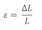
When an external force P acts on an elastic material (test specimen), it creates a stress that in turn causes deformation ΔL of the specimen. A tensile force increases the original length L of the test piece to L + ΔL. The ratio of ΔL to L is defined as strain ε (also called normal strain or longitudinal strain). Strain is usually denoted by ε and expressed in µm/m (microstrain). If a compressive force P is applied, the original length L is reduced to L – ΔL.
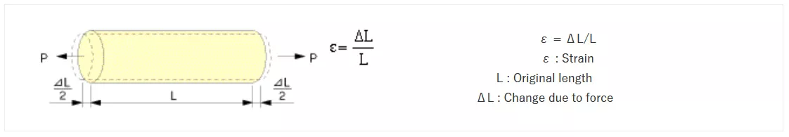
For a specimen with cross‑sectional area A, the resulting stress σ is defined as P / A. In a one‑dimensional stress/strain state, strain ε is proportional to stress σ, following the relationship:
where E is the elastic modulus of the material and applies as long as the stress remains below the material’s elastic limit.
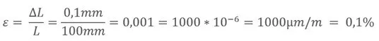
Because strain ε is a ratio of ΔL to L, it is a dimensionless quantity and is typically represented in microstrain (1 × 10⁻⁶). For example, if L = 100 mm and ΔL = 0.1 mm, the strain ε is expressed as 1000 × 10⁻⁶ or 1000 µm/m.
What is a Strain Gauge?
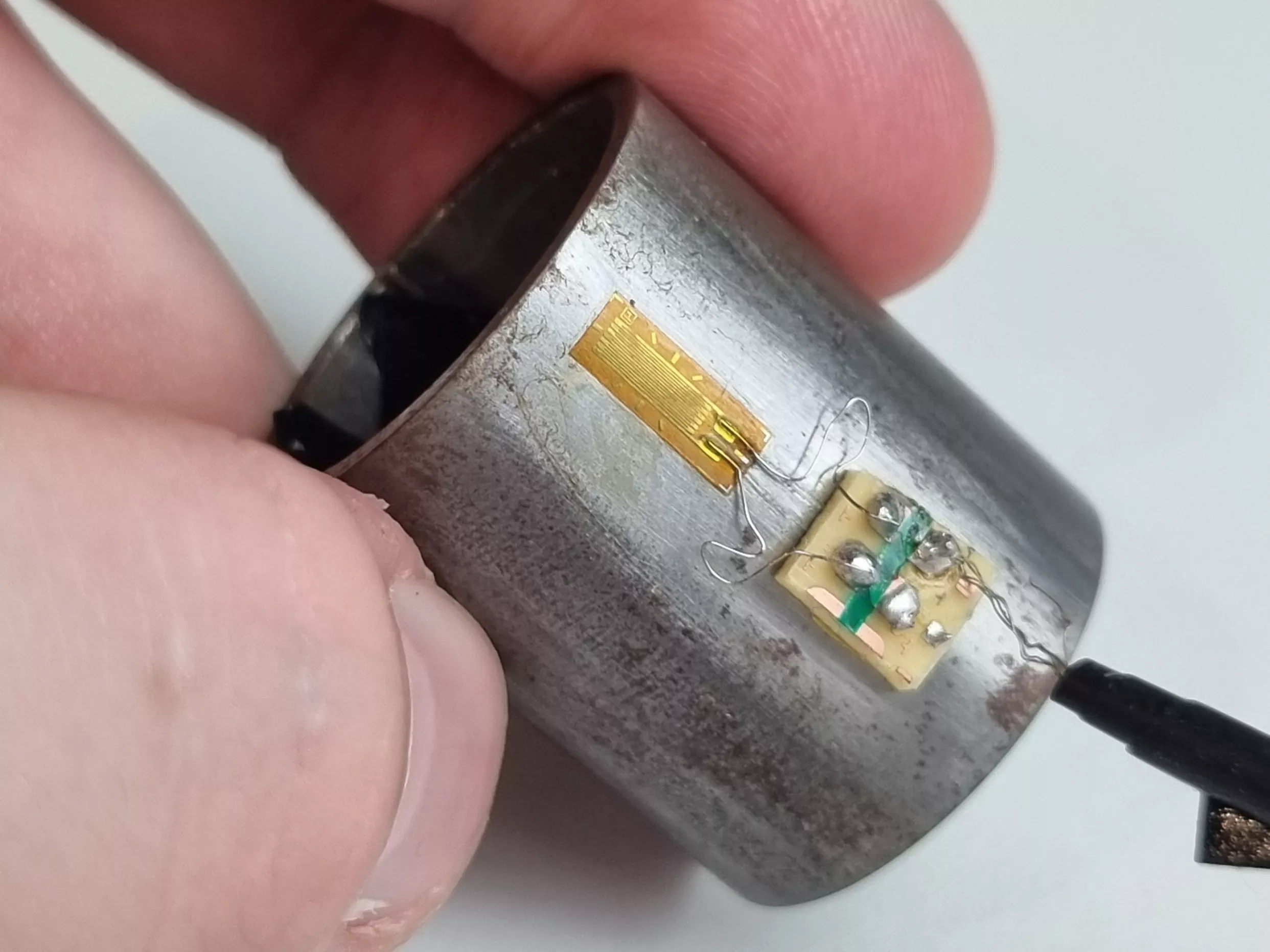
Once a strain gauge (also abbreviated as SG or DMS) is bonded to a test specimen and force is applied, the specimen deforms. This deformation causes a corresponding change in the electrical resistance of the strain gauge.
A strain gauge consists of a fine electrical resistance material in a grid pattern, typically made from either wire or a photolithographically etched metal foil (such as Konstantan or Karma) mounted on an insulating backing. In many cases, lead wires are attached to the grid to connect it to measurement electronics.
How a Strain Gauge Works
Strain gauges convert mechanical strain into a measurable change in electrical resistance. When the specimen — and with it the bonded strain gauge — is stretched or compressed, the gauge’s resistance changes proportionally. This change is detected and quantified using a Wheatstone bridge circuit, enabling highly precise strain measurement.
In practice, the strain gauge’s gage factor (K‑factor) quantifies its sensitivity by relating the relative change in resistance to the relative strain. Modern measurement systems use quarter‑, half‑, or full‑bridge configurations, depending on the application and required accuracy.
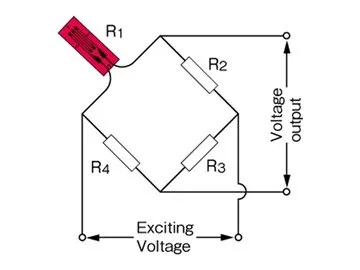
Since the change in resistance is very small, a Wheatstone bridge circuit is required. It allows even the smallest resistance changes to be converted into a measurable voltage change.
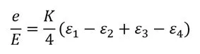
The bridge imbalance is the difference between the voltages across the two voltage dividers (R1, R2 and R3, R4).
In the case where R1 = R2 = R3 = R4, the bridge is balanced, and the bridge output voltage is zero.
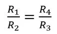
From the equation, it can be seen that the bridge is balanced when the following condition is met:
R1=R2=R3=R4
R1=R2 und R3=R4
R1/R2 und R3/R4
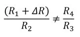
If the strain gauge (R1) is compressed or stretched, it undergoes a change in resistance ΔR. As a result, the bridge is no longer balanced.
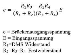
The circuit’s output voltage is calculated using the formula shown on the right.
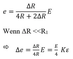
Here, R = R1 = R2 = R3 = R4. The resistance of the strain gauge changes due to strain and becomes R + ΔR. As a result, the output voltage Δe (the change caused by the strain) is given by the following formula:
Here, K is the gauge factor of the strain gauge and ε is the strain. In general, the approximation formula shown on the right can be used.
When measuring with a strain gauge (SG), it is connected to a strain gauge amplifier. The amplifier completes the strain gauge to form a Wheatstone bridge using internal precision resistors and supplies the bridge with an excitation voltage.
The measured strain is displayed on a digital readout and/or provided as an analog output signal.
Selection of Strain Gauges
There are various series of strain gauges available. Each series has its own limitations regarding temperature resistance, fatigue behavior, and maximum measurable strain. In addition, the measurement environment (external influences such as humidity, vibration, or chemicals) plays a critical role in the durability and reliability of the measurement. All these factors should be carefully evaluated before selecting a strain gauge for a specific application.
Benefits of Strain Gauges
- Simple design with low weight and compact size
- Short gauge lengths allow for localized, point-specific measurements
- Suitable for high-frequency dynamic measurements
- Simultaneous measurement at multiple points and remote data acquisition
- Electrical output enables easy signal processing and integration


Do you have questions regarding DMS?
We are happy to help you choose the right sensor for your application!