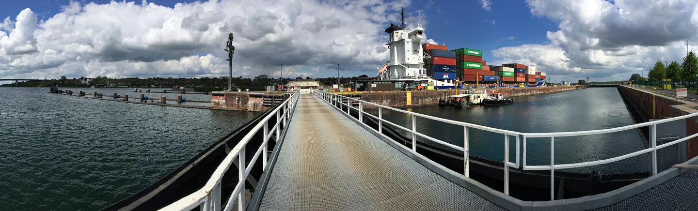
About the Kiel-Holtenau lock system
For this purpose, measurement specialist Althen developed customised measurement solutions for the project and supported the measurements for the company Tractebel Hydroprojekt GmbH, which was commissioned with preliminary investigations. The Kiel-Holtenau lock system is one of the two entrances to the Kiel Canal, which connects the North Sea and the Baltic Sea. The importance of the waterway for the European transport of goods is immense; the Kiel Canal is the busiest man-made sea shipping route in the world.
The Great Lock
With the high volume of ships in the NOK, it is important that the two lock systems function smoothly. At present, only the Great Lock with its two lock chambers can be used (effective length 310 m, effective width 42 m), as the Small Lock is currently being rebuilt. However, there is also a need for modernisation of the Great Lock, since the gearboxes of the lock gates were last renewed in the 1960s. Preliminary tests therefore had to be carried out during on-going operation - the biggest challenge in this project.
Data of the existing lock gate system
The Wasserstraßen-Neubauamt Nord-Ostsee-Kanal assigned the engineering service provider Tractebel Hydroprojekt with the preliminary investigations and Tractebel brought Althen GmbH Mess- und Sensortechnik on board for the realisation of the measurements. The aim was to determine relevant characteristic data of the existing lock gate system, e.g. occurring load peaks. In order to achieve precise dimensioning of the new lock drives and to be able to recognise and eliminate any problems that might occur, real measured values were a precondition - also for comparison with outdated data from the 1960s.
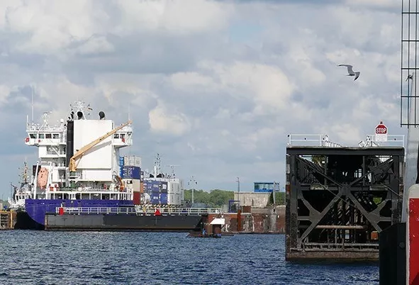
In the background, the huge lock gate (length: 42 m) of one of the two lock chambers closes after the ship has entered. The replacement lock gate in the foreground shows the complex construction: A lock gate not only consists of a flat wall, but is a structure several metres wide and projects about 14 metres into the water. Below the water surface, it is equipped with ballast tanks to ensure the buoyancy of the gate, depending on the requirements. Picture: ©Althen GmbH Mess- und Sensortechnik.
Measuring without design modifications
The Althen company has been active in the field of hydraulic engineering since its foundation in 1978. In addition to providing components such as force and displacement transducers, inclination sensors and measuring amplifiers, Althen also provides support and advice during construction, commissioning and in the event of any technical problems. If necessary, special solutions are developed - as in this case. It was necessary to consider how the goal could be achieved with as little effort as possible in terms of design changes to the system. The chosen solution with specially developed load measuring bolts met this requirement and the lock system could be returned to its original condition within a few minutes after the completion of a series of measurements.
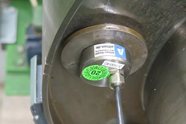
Development of specific load pins
To determine the shear and tension forces that occur when the sliding gates are moved, bolt connections between the two push rods and the actual gate element were replaced by specially developed load measuring bolts. The customer measured several clevises on the push rods and Althen developed a corresponding pin type. The same procedure was followed for the shear pins in the couplings: The four shear pin couplings in the two drive lines between the gear unit and the drive pinions allow the drive torque to be measured during gate travel. Here, too, there is no standard type of load cell, but Althen designed specific load pins for this application. Taking the lever arm into account, the torque could be determined from this.
Consider development effort in planning
Special developments always mean a significant extension of the project time, which must already be taken into account in the planning effort. This project required a total of half a year's lead time before the actual measurements - on the one hand because of the in-house developments, and on the other hand because the measurements had to take place during ongoing operation. It was checked when closures were possible and when the lock system had to be ready for use again. The closures for the measurements and the corresponding assembly and disassembly then took place for only a few hours at a time. Especially at night, the operation had to run smoothly. A particular challenge was the enormous amount of cabling, which had to be partially removed after each measurement.
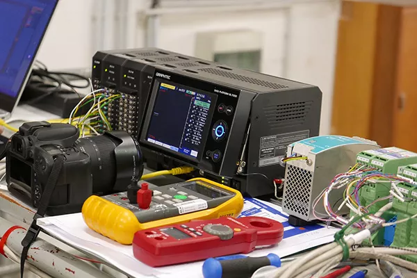
Further services provided by Althen were the signal evaluation of rotary encoders to record the position of the sliding gates, a documentation of the motor power based on the existing control signals as well as the recording of all determined measurement data with a data logger of the type Graphtec GL7000. With the measurement results now available, the original data and the previous theoretical calculations could be validated. In addition, the detailed information obtained enables further optimisation of the lock system.

Related products
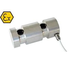
LAU Pin Load Cell (ATEX)
- Measuring range: 0 - 5 to 0 - 20 ton
- Stainless steel 17-4 PH construction
- Combined error ≤±0.1%
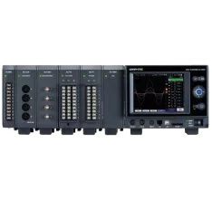
GRAPHTEC Data Platform GL7000 System
- Digital interfaces USB 2.0 and Ethernet
- 7 types of Input Modules
- 4 types of Function Modules
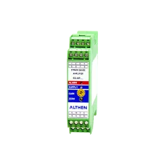
SG-KP Strain Gauge Amplifiers
- Supply voltage 10 - 18 VDC / 18 - 30 VDC
- Analogue output 0 - 10 V / ±10 V / 4 - 20 mA
- Plastic enclosure (IP20) for DIN-top hat rail mounting