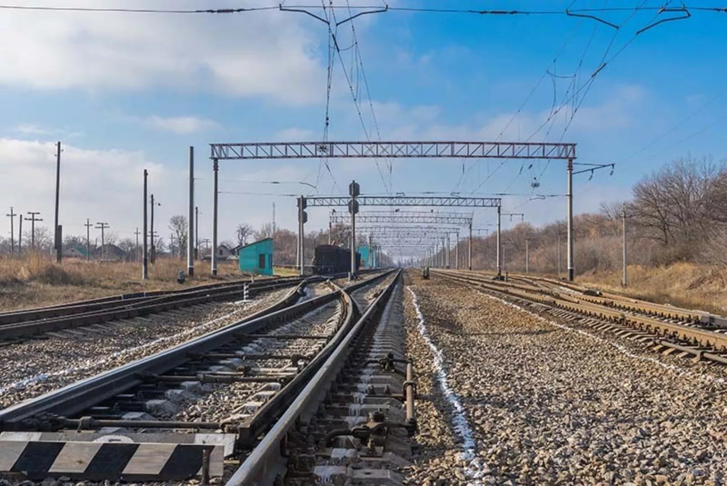
Challenge in rail transport: validation under real operating conditions
A provider in the rail technology sector needed a robust measurement solution to validate vehicle dynamics and track loading during the development of new rail vehicles. Existing methods offered only limited insight into the real forces at the wheel–rail interface—especially under changing loads and varying guidance conditions.
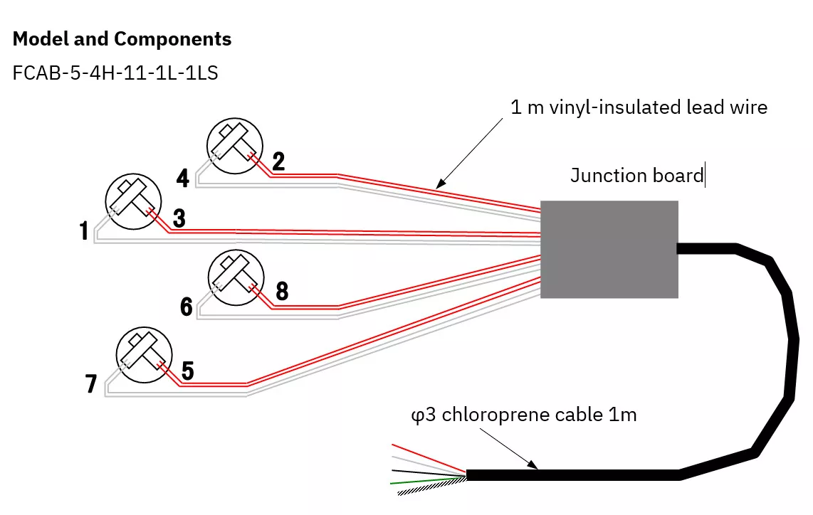
To precisely monitor the stresses on rail vehicles, a measurement system was developed that captures the vertical wheel load force and the lateral forces directly at the rail. The solution is based on FCAB-5 strain gauges mounted in a Wheatstone bridge configuration, reliably filtering out unwanted measurement components.
Customer expectations and requirements
The goal was to accurately measure:
- the vertical wheel load, and
- the lateral forces.
Both positive and negative force components needed to be clearly distinguished and detected without interference. Especially important to the customer were high measurement accuracy, a robust and long-lasting installation directly at the rail, and reliable differentiation between longitudinal and lateral forces.
Installation and wiring
The strain gauges were mounted at a 45° angle to the rail’s main axis at the specified locations on the rail web/flange (for wheel load force) and on the rail foot (for lateral force).
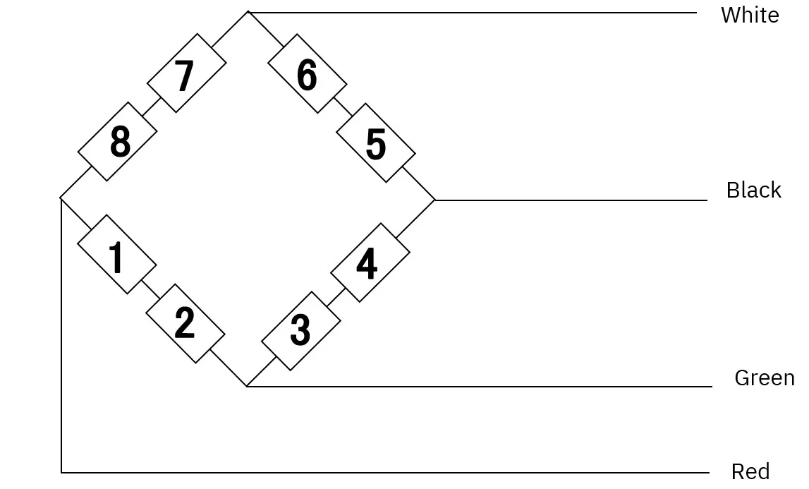
A total of eight strain gauges were used and connected via a terminal board in a Wheatstone bridge configuration.
Wheel load measurement
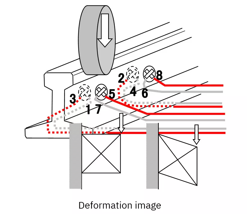
A strain gauge mounted on the side of the rail at a 45° angle undergoes a rhombus-shaped deformation at the measurement point under wheel load.
Gauges 1, 2, 5, and 6 provide positive output signals, while gauges 3, 4, 7, and 8 provide negative output signals. This results in a positive bridge output when a wheel load force is applied.
-
Reliable separation of wheel load and lateral forceThanks to the 45° mounting and Wheatstone bridge configuration, vertical and lateral forces can be clearly distinguished.
-
High measurement accuracy under real operating conditionsMounting directly on the rail and targeted calibration enable precise results despite environmental influences.
-
Compensation of unwanted influences through an 8-gauge configurationSystematic signal processing eliminates interference components and increases the informative value of the measurement data.
-
Robust, field-ready installationSuitable for long-term use in railway environments—featuring durable cables, protective materials, and stable bonding.
Calibration
After installing the strain gauges, a load test must be carried out to determine calibration factors (the relationship between strain or bridge output and the applied load). Calibration is necessary to account for installation differences and the site-specific contact conditions between wheel and rail.
Mechanical considerations
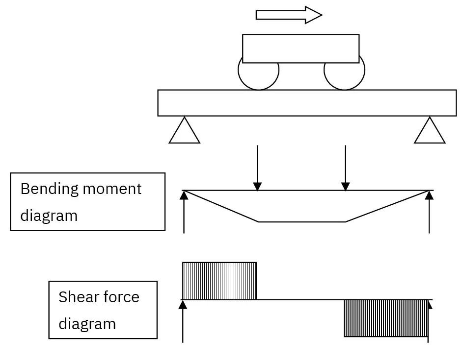
Between two wheels, the bending moments are equal in magnitude, and there is no resulting shear force between the wheels. Since the strain gauges are installed at a 45° angle, the output signal is primarily related to shear strain. In theory, shear strain is linked only to the wheel load force; in practice, however, lateral forces and the specific contact conditions between wheel and rail also influence the output signal.
To minimize these effects, eight strain gauges are used and their signals are averaged to eliminate unwanted components.
Effect of the spacing between strain-gauge groups
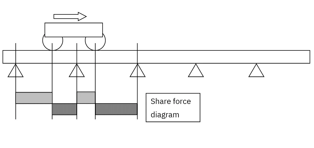
If the distance between the strain-gauge groups is reduced from 1000 mm to 150 mm, the duration of the applied load decreases as the wheel passes over.
The amplitude of the output signal is expected to remain largely unchanged; however, recalibration is required to verify and, if necessary, update the relationship between load and output signal.
Results and benefits
- Positive bridge outputs under real wheel load conditions
- High signal quality despite environmental influences
- Shear-strain measurement enables differentiation between vertical and lateral forces
- The system remains calibration-accurate even with reduced sensor spacing
The system proved convincing thanks to its practical suitability and ease of integration—an important step toward data-driven optimization of rail vehicles. Althen Sensors & Controls not only supplied the appropriate sensors, but also supported the application design, calibration, and integration. With our application-specific expertise, we delivered a reliable, robust, and low-maintenance measurement solution for harsh rail environments.


What is your project?
Do you have any questions about measurements with strain gauges? We are happy to help!