
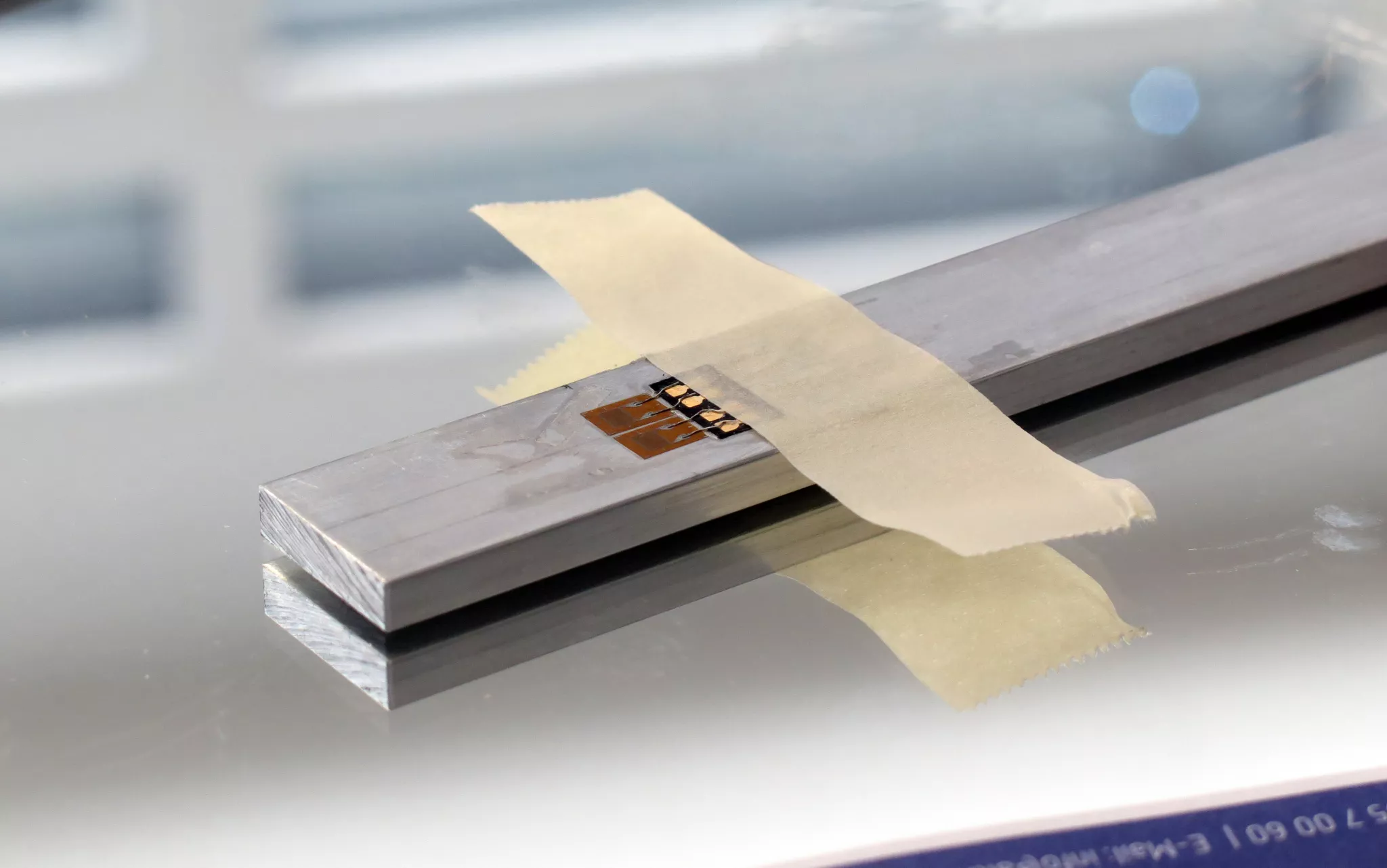
When a single strain gauge is used in a quarter-bridge circuit, the connecting leads influence the measurement result. Each lead has an electrical resistance that depends on its length, cross-section, material and temperature. The longer and thinner the lead, the higher its resistance.
Of particular importance is not only the fixed lead resistance, but also the way it changes with temperature fluctuations. This can cause zero-point errors, reduced sensitivity and apparent strain. The appropriate wiring configuration depends on the lead length, temperature conditions, accuracy requirements and the measurement amplifier being used.
The wiring configuration compensates only for influences caused by the connecting leads. It does not automatically compensate for the thermal expansion of the component, the temperature behaviour of the strain gauge grid or an unsuitable match between the strain gauge and the component material. These effects are discussed in the article Temperature Compensation for Strain Gauges.
2-Wire Configuration
With a 2-wire configuration, the strain gauge is connected to the measurement amplifier via two leads. The resistances of the outgoing and return leads are connected in series with the strain gauge and therefore become part of the active bridge arm. This has two effects: firstly, the additional lead resistance changes the bridge balance. Secondly, the effective sensitivity of the measurement circuit decreases because the resistance change of the strain gauge appears smaller in relation to the total resistance of the strain gauge and the leads.
If the temperature of the leads changes, their resistance changes as well. The bridge detects this change as apparent strain. The 2-wire configuration is therefore particularly sensitive to temperature fluctuations.
The 2-wire configuration is mainly suitable for very short leads, thermally stable conditions and measurements with limited accuracy requirements. The fixed influence of the cable resistance can be taken into account mathematically or by configuring the measurement amplifier accordingly. However, temperature-dependent changes in cable resistance cannot be completely eliminated in this way.
3-Wire Configuration
The 3-wire configuration is the most commonly used connection method for strain gauge quarter bridges. An additional lead makes it possible to distribute the effects of lead resistance across two adjacent bridge arms or to compensate for them actively in the measurement amplifier.
In the conventional passive 3-wire circuit, approximately equal lead resistances are located in adjacent bridge arms. If they change by the same amount as a result of the same temperature change, these changes affect both halves of the bridge to approximately the same extent and therefore largely cancel each other out in the output signal.
The relevant leads should:
- be made of the same material,
- have the same cross-section,
- be as close as possible to the same length,
- be exposed to largely the same temperature conditions.
With a regulated 3-wire circuit, the measurement amplifier can additionally measure the voltage drop across one lead and adjust the excitation accordingly. In this case, the effect of the fixed lead resistance on sensitivity can also be largely compensated. The exact function depends on the measurement amplifier being used.
The physical gauge factor of the strain gauge is not changed by the leads. Whether an additional sensitivity correction is required depends on the circuit configuration and the settings of the measuring instrument. The 3-wire configuration therefore primarily reduces the fixed and temperature-dependent influence of the connecting leads. Apparent strain of the strain gauge itself or thermal expansion of the component is not compensated in this way.
4-Wire Configuration
With a 4-wire configuration, two additional connections are available to determine the voltage drop or the actual electrical conditions at the measuring point more accurately. This allows lead effects to be reduced more effectively than with a simple 2-wire circuit.
However, the term is not used entirely consistently in strain gauge measurement technology. Depending on the measurement amplifier, it may refer, for example, to a Kelvin-type measurement, a regulated quarter-bridge circuit or a special manufacturer-specific compensation circuit. The terminal assignment and operating principle must therefore always be checked against the circuit diagram of the measurement amplifier.
With a correctly supported 4-wire circuit, both the fixed lead resistance and temperature-dependent changes can be compensated very effectively. However, it would be misleading to state generally that the influence of the leads is always eliminated completely. Asymmetrical leads, contact resistances, temperature gradients and incorrect wiring can still cause measurement errors.
The 4-wire configuration is particularly suitable for:
- long connecting leads,
- high accuracy requirements,
- changing temperature conditions,
- precise shunt calibrations,
- measurement tasks involving very small strains.
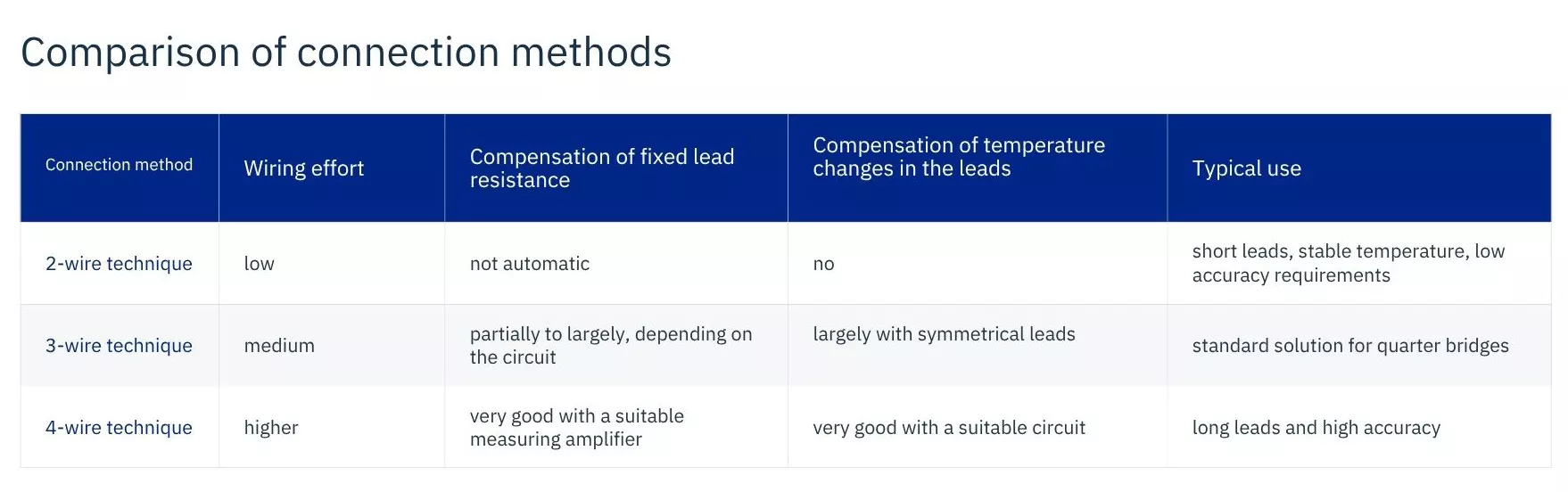
The table is deliberately kept general. The decisive factor is always which connection method is supported by the specific strain gauge measurement amplifier. Measuring instruments differ, among other things, in their bridge completion, regulation methods, sense function and mathematical cable correction. For quarter bridges, for example, NI and ME-Systeme explicitly specify device-specific completion resistors and connection configurations.
Practical Wiring Guidelines
All conductors of a compensated circuit should, wherever possible, be routed together in the same cable. This ensures that they experience similar temperature changes. Differences in lead length, cross-section or material reduce the effectiveness of the compensation.
In addition, make sure that:
- contact and solder joints have low resistance and remain stable,
- cables are provided with strain relief,
- shielded and/or twisted-pair cables are used in environments susceptible to electrical interference,
- leads are not routed directly alongside motor or power cables,
- the configured bridge type corresponds to the actual wiring,
- zero adjustment and a plausibility check are carried out before measurement.
For long leads, it should also be checked whether the measurement amplifier supports regulated excitation, cable compensation or a sense function.
Conclusion
The 2-wire configuration is simple, but it is sensitive to both the fixed resistance of the connecting leads and temperature-related changes in that resistance. For strain gauge quarter bridges, the 3-wire configuration is therefore usually the most appropriate standard solution. It largely reduces lead effects, provided that the conductors involved have comparable electrical and thermal properties.
With suitable instrument support, the 4-wire configuration can provide even more accurate compensation. However, its operating principle is not identical for all measurement amplifiers, which means that the wiring and configuration must be checked against the manufacturer's documentation.
An important distinction should be kept in mind: the wiring configuration compensates only for effects caused by the connecting leads. Temperature effects associated with the component, the strain gauge and the measuring point require additional measures, as explained in the article Temperature Compensation for Strain Gauges.