
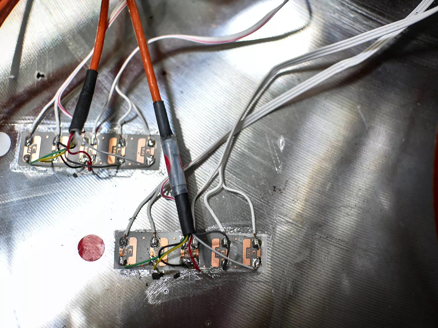
This article explains how thermal and apparent strain occur, what self-temperature-compensated strain gauges can achieve, and when dummy strain gauges, half- or full-bridge circuits, and mathematical corrections are useful.
Temperature changes can significantly affect the result of a strain gauge measurement. Temperature affects not only the strain gauge itself, but also the component, adhesive, lead wires, and the entire measurement chain. For precise measurements, these influences must be distinguished from one another and reduced using suitable measures.
Why does temperature affect strain gauge measurements?
A strain gauge changes its electrical resistance when it is mechanically stretched or compressed. A change in temperature can also cause a change in resistance. At the same time, the component expands or contracts according to its coefficient of thermal expansion.
Initially, the measuring amplifier cannot distinguish whether a change in resistance was caused by the mechanical load being investigated, by temperature, or by both effects together. Without suitable compensation, measurement deviations can therefore occur.
The most important temperature effects include:
- thermal strain of the component,
- temperature-dependent resistance change of the measuring grid,
- apparent strain of the installed strain gauge,
- temperature dependence of the gauge factor,
- self-heating caused by bridge excitation,
- temperature effects on the adhesive, backing, and lead wires.
These effects should be considered separately because they require different compensation measures.
Thermal strain of the component
Almost all materials change their dimensions with temperature. For a uniform temperature change, free thermal strain can be approximated by:
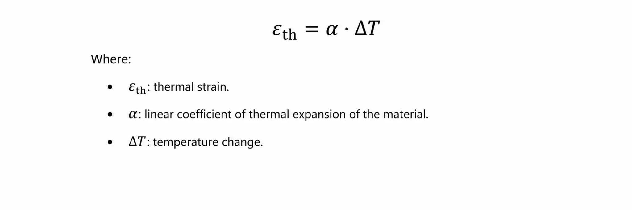
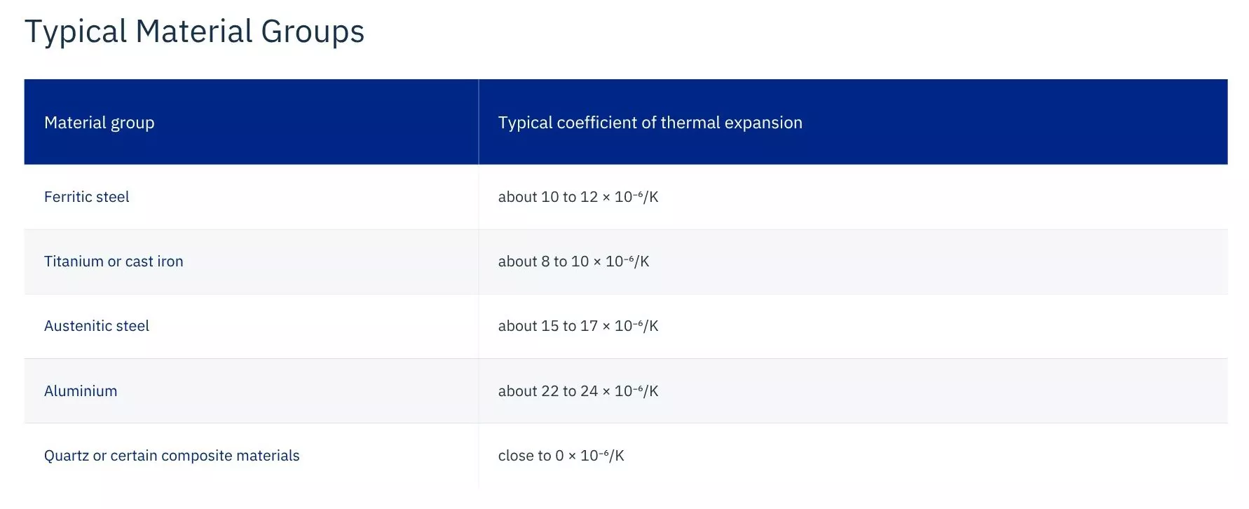
For example, if a freely movable steel component with a coefficient of thermal expansion of approximately [value as shown in source formula] is heated by 20 K, the resulting thermal strain is approximately:

This deformation is physically real. Whether it is considered a useful signal or a disturbance depends on the measurement task.
When investigating thermal expansion, this strain is intended to be measured. In a mechanical load measurement, however, the aim is often to measure only the portion caused by force, pressure, bending, or torsion.
Free and restrained thermal expansion
It is important to distinguish between free and restrained thermal expansion. If a component can expand freely, thermal strain occurs, but ideally no thermally induced mechanical stress is generated.
If expansion is restricted by clamping, connections, or other components, additional thermal stresses occur. These stresses are real mechanical loads and should not automatically be removed as measurement errors.
A typical example is a rigidly restrained pipeline. When the pipeline heats up, it cannot expand freely in length. The resulting stresses are relevant to the structural assessment.
Before applying any temperature correction, it should therefore be determined which measurand is required:
- total component strain,
- only mechanically induced strain,
- free thermal expansion,
- stress resulting from restrained thermal expansion.
Temperature dependence of strain gauge resistance
Even without mechanical loading, the electrical resistance of the measuring grid changes with temperature. This is caused by the temperature coefficient of the resistance material used.
In simplified form:

This temperature-induced resistance signal is detected by the Wheatstone bridge in essentially the same way as a mechanically induced resistance change. The temperature behaviour of the strain gauge must therefore be matched to the component material and the intended temperature range.
What is apparent strain?
Apparent strain is the temperature-dependent output signal of a strain gauge installed on a component that does not correspond to the mechanical load-induced strain being measured.
It results particularly from the interaction of:
- thermal expansion of the component,
- temperature coefficient of the measuring-grid resistance,
- temperature behaviour of the backing and adhesive,
- matching of the strain gauge to the component material.
Apparent strain is therefore not a single material property, but the result of the complete installed strain gauge system.
In simplified terms, it can be understood as the difference between the temperature behaviour of the strain gauge and the thermal expansion of the component. In practice, it is often specified as a characteristic curve versus temperature.
Self-temperature-compensated strain gauges minimise this apparent strain within a defined temperature range, but do not eliminate it completely. For suitable combinations of strain gauge and material, Kyowa, for example, specifies the remaining apparent strain within a defined compensation range.
What happens if the strain gauge is incorrectly matched?
If a strain gauge is used whose temperature compensation does not match the component material, significant apparent strain can occur.
A strain gauge designed for steel but installed on aluminium is a typical example. Aluminium expands approximately twice as much as many steels for the same temperature change. The temperature behaviour of the strain gauge may therefore be unable to compensate sufficiently for this difference.
The result can be a signal that changes with temperature even though the mechanical load remains unchanged.
Limits of self-temperature compensation
“Self-temperature-compensated” does not mean “temperature-independent”. The following residual errors may still occur:
- deviation of the actual component material from the nominal compensation value,
- temperature gradients across the measuring point,
- differences between strain gauge batches,
- temperature dependence of the gauge factor,
- adhesive and backing effects,
- ageing,
- self-heating,
- temperature effects on the lead wires.
Selecting the appropriate self-temperature-compensated strain gauge
The actual coefficient of thermal expansion of the component material should be known when selecting the strain gauge. General material tables are not always sufficient, because alloy composition, heat treatment, fibre orientation, or manufacturing processes can affect the value.
Particular care is required with composite materials. Their coefficient of thermal expansion may be direction-dependent and can differ significantly in the fibre direction compared with the transverse direction.
Selection should therefore take at least the following factors into account:
- component material and coefficient of thermal expansion,
- temperature range,
- static or dynamic measurement,
- measurement duration,
- strain gauge series,
- adhesive,
- protective system,
- required accuracy.
The specified temperature compensation applies only within the specified temperature range and under defined installation conditions.
Dummy strain gauges for temperature compensation
A dummy strain gauge is a second, unloaded strain gauge installed in an adjacent arm of the Wheatstone bridge. The active strain gauge detects both mechanical strain and temperature effects. The dummy strain gauge, by contrast, should experience only the same temperature effect. If both are wired correctly, their temperature-induced resistance changes can largely cancel each other out in the bridge output.
Requirements for a dummy strain gauge
For the compensation to work, the dummy strain gauge should:
- be of the same type and preferably from the same batch,
- be installed on a comparable material,
- experience the same temperature as the active strain gauge,
- remain mechanically unloaded,
- be bonded using the same adhesive and a comparable installation setup.
A common solution is to install the dummy strain gauge on an unloaded reference piece made from the same material and position it as close as possible to the actual measuring point.
Limits of dummy compensation
A dummy strain gauge only works reliably if both strain gauges experience the same temperature profile.
Problems occur when:
- the dummy strain gauge is located too far away,
- the two measuring points heat up at different rates,
- a temperature gradient exists,
- the dummy strain gauge is unintentionally mechanically loaded,
- different substrates are used,
- the adhesive layer or protective coating differs.
During rapid temperature changes, differences in thermal time constants alone can generate temporary measurement errors.
Temperature compensation with half bridges
A half bridge uses either two active strain gauges or one active and one compensating strain gauge. Depending on the arrangement, common temperature effects can largely cancel each other out in the bridge output.
A typical example is a bending half bridge. One strain gauge is located on the tensile side and the second on the compressive side of a beam. Under mechanical bending, their resistances change in opposite directions. Under a uniform temperature change, however, both strain gauges react similarly.
With correct wiring, the mechanical measurement signals add together, while temperature effects acting in the same direction are largely compensated.
The compensation requires both strain gauges to:
- be of the same strain gauge type,
- experience similar temperatures,
- be correctly positioned in adjacent bridge arms,
- be installed on thermally comparable areas.
A half bridge does not automatically compensate for every temperature effect. Temperature gradients between the measuring points remain particularly critical.
Temperature compensation with full bridges
A full bridge uses four active strain gauges. This configuration is frequently used in force, weighing, pressure, and torque transducers.
With a suitable arrangement, two strain gauges are subjected to tension and two to compression. The mechanical signals add together in the bridge output. Similar temperature-induced resistance changes, on the other hand, act similarly in all bridge arms and can largely cancel each other out.
A full bridge therefore provides good conditions for temperature compensation and high sensitivity. Nevertheless, temperature effects may still occur, for example due to:
- different temperatures at the four measuring points,
- variations in strain gauge properties,
- temperature dependence of the measuring body,
- adhesive creep,
- temperature dependence of the gauge factor,
- amplifier drift.
For high-precision transducers, additional temperature-dependent zero-point and sensitivity corrections are therefore used.
The Wheatstone bridge does not automatically compensate for temperature
A common misconception is that every Wheatstone bridge automatically eliminates temperature effects. A bridge can only compensate for effects that occur approximately equally in the relevant bridge arms and cancel each other out due to the wiring configuration.
A quarter bridge with only one active strain gauge does not provide complete temperature compensation without additional measures. A half or full bridge can reduce temperature effects more effectively, provided the strain gauges are exposed to comparable thermal conditions.
The exact effect therefore always depends on the strain gauge arrangement, type of loading, and bridge configuration.
Influence of lead wires
The electrical resistance of the lead wires also changes with temperature. Particularly in quarter-bridge circuits, this can cause additional bridge imbalance.
A 2-wire circuit is particularly sensitive to this effect. In a 3-wire circuit, comparable lead resistances are distributed across adjacent bridge arms so that their temperature-dependent changes can largely compensate for each other.
Kyowa explicitly describes 3-wire technology as a method for reducing the temperature influence of lead wires.
It is important to make a distinction: the wiring method compensates only for temperature-dependent resistance changes in the wires. It does not compensate for thermal expansion of the component or apparent strain of the strain gauge.
Temperature dependence of the gauge factor
The gauge factor describes the sensitivity of the strain gauge:

For many strain gauges, a gauge factor of approximately 2 is specified at room temperature. However, this value can change with temperature. This creates a sensitivity or scaling error. Even if the zero point were fully corrected for temperature effects, the same mechanical strain could produce a slightly different output signal at different temperatures.
For measurements over a wide temperature range, it should therefore be checked whether the manufacturer provides a temperature characteristic or correction factor for sensitivity.
Self-heating of the strain gauge
The strain gauge is electrically loaded by the bridge excitation voltage. The dissipated power can be approximated by:

A higher excitation voltage improves the output signal, but also increases power dissipation. If the heat cannot be dissipated sufficiently, the measuring point heats up. The risk is particularly high with:
- low-resistance strain gauges,
- small measuring-grid areas,
- plastics and composite materials,
- thin components,
- high ambient temperatures,
- long-term static measurements.
With plastics that have poor thermal conductivity, even relatively low excitation voltages can cause relevant self-heating.
How can self-heating be identified?
A typical indication is a zero signal that changes slowly after the bridge excitation is switched on and stabilises only after a certain period of time. To investigate this, the zero signal can be compared at different excitation voltages. If the drift changes significantly with the excitation voltage, self-heating is a likely cause.
Possible countermeasures include:
- reducing the excitation voltage,
- using a higher-resistance strain gauge,
- selecting a larger measuring grid,
- improving heat dissipation,
- reducing the measurement duration or power-on time,
- using pulsed excitation if supported by the measurement system.
Temperature influence on the adhesive and protective system
A strain gauge can only measure correctly if the component strain is reliably transferred to the measuring grid. The adhesive, backing, and protective coating are therefore part of the measurement system. Temperature can cause the following effects in these materials:
- creep,
- relaxation,
- embrittlement,
- softening,
- changes in adhesion,
- different thermal expansion,
- ageing.
A strain gauge suitable for high temperatures cannot be operated across its intended range if the adhesive, lead wires, or protective system have a lower permissible temperature. The maximum operating temperature must therefore always be checked for the complete measuring point.
Mathematical temperature correction
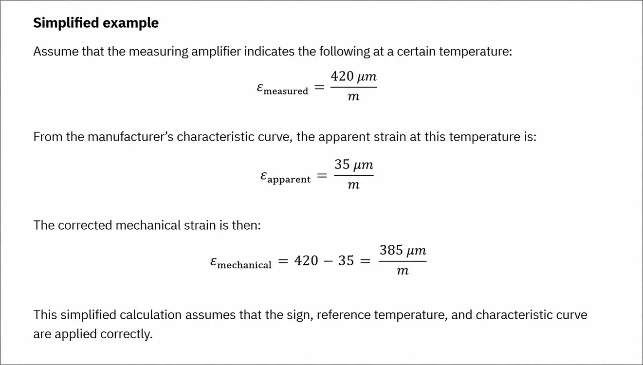
Self-temperature compensation and bridge circuitry may not be sufficient for applications with high accuracy requirements. In such cases, the remaining temperature signal can be corrected mathematically. Manufacturers often provide a characteristic curve or polynomial describing apparent strain as a function of temperature.
The basic procedure is:
- Measure the temperature directly at or close to the strain gauge measuring point.
- Determine the apparent strain for the measured temperature using the characteristic curve or polynomial.
- Subtract the temperature-induced component from the raw signal.
- If necessary, account for the temperature dependence of the gauge factor.
Reference temperature and zero point
Temperature characteristic curves generally refer to a defined reference temperature. The bridge zero adjustment is also carried out at a specific temperature.
If the temperature subsequently changes, the correction must be applied relative to this initial condition.
It is therefore important to document the following:
- temperature during zero adjustment,
- temperature during measurement,
- warm-up time of the measurement system,
- strain gauge type and batch,
- compensation characteristic used,
- bridge configuration,
- excitation voltage.
If the zero adjustment is repeated after every temperature change, a real thermal or mechanical signal component may unintentionally be removed.
Temperature measurement at the strain gauge measuring point
For mathematical correction, the actual temperature at the measuring point must be known. The ambient air temperature is often insufficient. The component can be significantly warmer or colder than its surroundings due to solar radiation, frictional heat, electrical power dissipation, or internal processes.
Suitable temperature sensors include:
- thermocouples,
- Pt100 or Pt1000 sensors,
- thermistors,
- integrated temperature sensors.
The temperature sensor should be installed as close as possible to the strain gauge without significantly affecting the local stiffness, heat distribution, or strain. During rapid temperature changes, the response time of the temperature sensor must also be considered.
Temperature gradients
A temperature gradient exists when different areas of the component or measuring point have different temperatures. Typical causes include:
- one-sided heating,
- solar radiation,
- local heating elements,
- friction,
- hot-gas or cold-gas flows,
- differences in heat dissipation,
- rapid temperature changes.
A temperature gradient can cause the active strain gauge, dummy strain gauge, and temperature sensor to experience different temperature profiles. Compensation is then incomplete.
Rapid transient processes are particularly critical. Even if all components eventually reach the same final temperature, differences in their thermal time constants can cause significant temporary measurement errors during the transition.
Examples for different materials
Steel
Steel has comparatively good thermal conductivity and a moderate coefficient of thermal expansion. With a suitably matched self-temperature-compensated strain gauge, temperature effects can often be controlled effectively. However, significant temperature gradients can still occur on large components or with one-sided heating.
Aluminium
Aluminium has a significantly higher coefficient of thermal expansion than steel. Correct temperature matching of the strain gauge is therefore particularly important. Its good thermal conductivity often reduces local self-heating, but does not prevent apparent strain if an unsuitable compensation code is used.
Plastic
Plastics often have a high coefficient of thermal expansion and low thermal conductivity. Both apparent strain and self-heating can therefore be particularly pronounced. In addition, the modulus of elasticity and viscoelastic behaviour of many plastics change with temperature. This means that not only the strain gauge signal but also the mechanical behaviour of the test specimen may be temperature-dependent.
Fibre-reinforced composites
For CFRP and GFRP, thermal expansion and thermal conductivity are often direction-dependent. The relevant coefficient of thermal expansion therefore depends on fibre orientation, laminate lay-up, and the position of the measuring point. A single general compensation value is often insufficient. For high-accuracy applications, experimental characterisation and separate temperature measurement are advisable.
Concrete and structures
Due to their mass, concrete components often react slowly to temperature changes. Significant temperature gradients can develop across the cross-section. In long-term measurements, moisture, solar radiation, daily cycles, and seasonal changes must also be considered. For structural health monitoring applications, temperature and strain should therefore be recorded together over extended periods.
How can temperature errors be identified?
Temperature-induced measurement deviations often show characteristic patterns:
- The zero signal changes after switch-on.
- The measured value follows the daily or ambient temperature profile.
- The signal changes even though the load remains unchanged.
- Heating and cooling produce different signal curves.
- Different measuring points drift differently.
- The measured value stabilises only after a longer waiting period.
- Drift changes with excitation voltage.
- The active and dummy strain gauges do not provide sufficient compensation during rapid temperature changes.
For diagnostic purposes, temperature, raw signal, excitation voltage, and time should be recorded together.
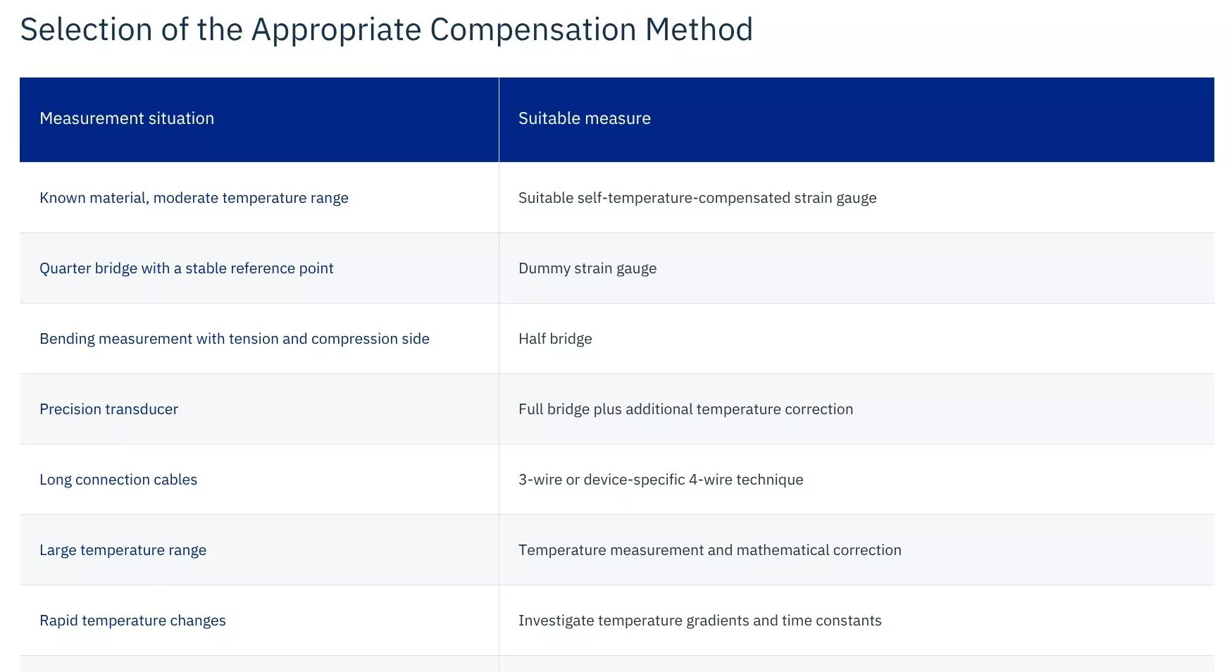
Practical checklist
Before taking measurements, the following questions should be answered:
- What material is present at the measuring point?
- What is its coefficient of thermal expansion?
- Is thermal strain the useful signal or an unwanted influence?
- What temperature range is expected?
- How quickly will the temperature change?
- Is a suitable self-temperature-compensated strain gauge available?
- Which bridge circuit will be used?
- Can a dummy strain gauge be installed under thermally comparable conditions?
- Is the lead-wire configuration temperature-compensated?
- Is there a risk of self-heating?
- Is the temperature measured directly at the measuring point?
- Is a manufacturer characteristic curve available for mathematical correction?
- Are the adhesive, cables, and protective system suitable for the temperature range?
- Can temperature gradients occur?
- How will the effectiveness of the compensation be verified?
Conclusion
Temperature compensation for strain gauges is not a single function, but the interaction of several measures. First, it must be determined whether the measured strain is caused by free thermal expansion, restrained thermal expansion, mechanical loading, or a temperature-dependent strain gauge signal.
A suitably matched self-temperature-compensated strain gauge reduces a large portion of apparent strain. Dummy strain gauges and half- and full-bridge circuits can additionally compensate for common temperature effects. 3-wire technology reduces the temperature influence of the lead wires, while mathematical correction can compensate for remaining deviations based on the actual temperature at the measuring point.
For reliable results, the strain gauge, component material, bridge circuit, adhesive, lead wires, protective system, and measuring amplifier must be considered as one complete measurement chain. Especially over wide temperature ranges, during rapid temperature changes, with materials that have poor thermal conductivity, and in long-term measurements, temperature should be measured directly at the measuring point and documented together with the strain signal.