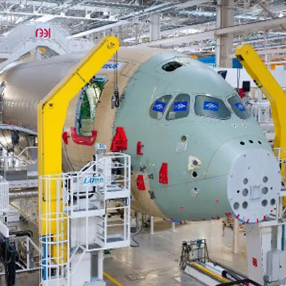
Like a high-tech jigsaw puzzle
The most important parts of the A350 XWB, such as the fuselage, wings, engines and tail unit, are manufactured at Airbus' European production sites in France, Germany, Spain and the United Kingdom. The A350 XWB Final Assembly Line (FAL) in Toulouse then assembles all the aircraft parts like a high-tech jigsaw puzzle. The A350 XWB's fuselage consists of three main parts - the front section, the center section and a tail section. All sections-including the landing gear-are assembled at the first main assembly station, the P50. Once this step is completed, the fuselage is transported to the P40 assembly station, where the wing and tail sections are joined. The final assembly line is extremely flexible. It can be used for both the A350-900 and -1000 models.

Assembly process
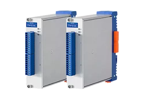
The process of joining and connecting the large assemblies is a complex task. Particularly in the case of components made of carbon fiber-reinforced plastic (CFRP), which are used in large quantities on the A350 XWB, gravity and ambient conditions lead to geometric deformations. To ensure reliable localization and positioning of the large aircraft parts, a the assembly system is supported by measurement technology. A series of multi-axis positioning systems lifts, moves and aligns the fuselage and wing structure to ensure optimal fit. To best protect the large parts during alignment, load cells mounted in the positioner's drive mechanism are used. They are used to monitor the forces acting on the structure during movement. Possible damage caused by stresses and strains on the parts during assembly is thus avoided. The entire assembly system contains 300 load cells. Single-axis load cells monitor stroke (Fz) and triaxial load cells monitor force during assembly (Fx, Fy and Fz). All load cells have a dual bridge output to allow redundancy in the system. The load cells are connected to a Gantner Q.bloxx measurement system. A total of 150 Q.bloxx A101 modules are used for primary force monitoring. In addition, 300 Q.bloxx A102 modules are used for redundant monitoring.
Functionality of the measuring system
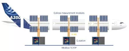
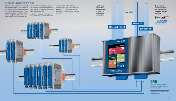
The distance between load cell and monitoring system can be up to 75 meters. Placing the signal converters close to the actual measuring points is one of the most important requirements when designing a measurement-based assembly system. The optimal channel granularity of the Q.bloxx, combined with the ability to freely combine and distribute modules, provides Airbus with maximum flexibility. The modules communicate via RS-485 with a centrally positioned Q.station controller, which performs the tasks of data acquisition, synchronization and control. Data is transmitted via a very efficient protocol with a baud rate of up to 48 MBaud. Despite the decentralized design, the measurement is performed synchronously with a jitter of less than 1 µs. This architecture ensures reliable measurement results with only minimal cabling effort. The monitoring system for the assembly line includes a Schneider Electric Safety PLC. The Q.station controller in open architecture communicates with the Safety PLC via mode TCP/IP. By separating the Q.station controller from the measurement modules, communication and compatibility with the monitoring system is significantly optimized. Another advantage for Airbus is the possibility of a controller exchange if the interface or performance requirements change - without major new investments.
Function and structure of the measuring solution
The Q.bloxx A101 and A102 feature on-board microprocessors, 24-bit A/D converters, anti-alias hardware filters, and full 3-way isolation up to 500 VDC on each channel. The measurement modules support sampling rates of up to 100 kHz per channel. Since the transmission of large amounts of raw data places a heavy load on network resources, each module is equipped with an FPGA. This enables complete signal conditioning and data processing directly at the point where the sensor data enters the measurement system. Thus, only data with process-relevant information, such as mean value, min/max and peak spike measurement, is sent to the monitoring system. This avoids long loading times and improves response times.
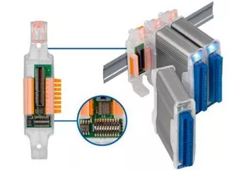
Q.bloxx for decentralized, fast and accurate measurement
The costs for the assembly of the passenger compartment amount to up to 40% of the total construction budget. Therefore, the reliable availability of the assembly system is of particularly high importance here. Each Q.bloxx module is connected to a socket that contains a built-in flash memory chip with a copy of the entire module configuration. This means that when a defective module is replaced, there is no need to manually reconfigure the new module or the monitoring system. Modules can be replaced while the system is running without having to turn off the power. In just 5 seconds, the configuration is copied from the socket to the new module. The measurement continues automatically as soon as the configuration is restored. The Q.bloxx "Hot Swap" function enables efficient maintenance and servicing of the measurement system, minimizing downtime and increasing the efficiency of the final assembly line.
Grafiek 1: @AIRBUS S.A.S. 2012 foto door e*m company / P. Pigeyre
overige foto's/grafieken: GI