Strain gauges are a fundamental tool in experimental stress and strain measurement. They enable highly precise capture of mechanical loads in a wide range of materials and components — from composite materials to welded joints. Below we present two typical and highly relevant practical application cases.
Testing Material Properties of Composite Materials (CFRP / GFRP)
Fiber‑reinforced composite materials such as CFRP and GFRP are increasingly used in safety‑critical applications — for example in mechanical engineering, aerospace, automotive, and energy technology. Due to their anisotropic structure, however, they impose specific demands on accurate strain measurement.
Material Anisotropy in Composite Materials
In composite materials, both the coefficient of thermal expansion (CTE) and the elastic modulus vary significantly depending on direction. Measured strains can differ markedly based on fiber orientation.
In particular, through‑thickness (laminate) direction can exhibit thermomechanical stresses that lead to cracking, microcracks, or delamination.
For correct interpretation of measurement results, accounting for material anisotropy is essential.
Use of Temperature‑Compensated Strain Gauges
To ensure reliable measurement data, temperature‑compensated strain gauges should be used, with a CTE as close as possible to the composite’s CTE in the measurement direction.
Typical reference values include:
- CFRP: BF series, approx. 3.5 × 10⁻⁶ / °C
- GFRP: F series, approx. 17 × 10⁻⁶ / °C
Since composite materials often have an elastic modulus of ≥ 10 GPa, a lower modulus in the strain gauge does not reduce measurement sensitivity.
Selecting the Right Gauge Length
Gauge length selection depends not only on the available bonding area but also on the fiber or weave pitch of the material. A gauge length of approximately 3 to 5 times the fiber pitch has proven effective in capturing representative mechanical behavior of the composite. Too short gauge lengths can overemphasize local effects, while too long ones can average out relevant stresses.
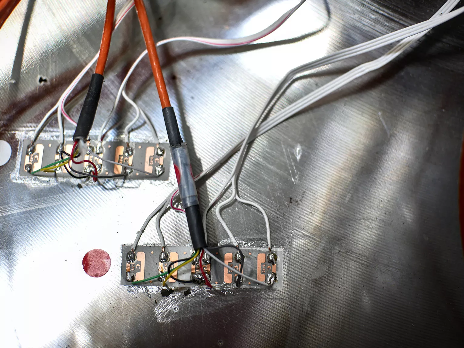
Proper Installation of Strain Gauges on CFRP / GFRP
Careful surface preparation is key:
- When sanding, avoid damaging or cutting the fiber structure, as this can distort both material properties and measurement results.
- Molded or injection‑molded parts may have release agent residues. These must be completely removed by thorough degreasing before bonding the strain gauge.
Matching products
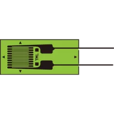
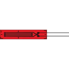
UBFLA Series Strain Gauges for Composite Material Use
- Stress limit 3% (30000×10-⁶ strain)
- Small strain gauge with one element
- Operational temperature (static): -30~+120°C
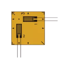
BFCA Series Strain Gauges for Composite Material Use
- Strain limit 3% (30000×10⁻⁶ strain)
- +10~+80°C temperature compensation
- Dual element 0°/90° plane type
BFLA Series Strain Gauges for Composite Material Use
- Strain limit 3% (30000×10⁻⁶ strain)
- Polyimide backing, Cu-Ni element
- Operational temperature: -20~+200°C
Our projects
Discover our projects related to materials testing.

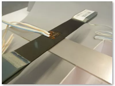
Strain Measurement on Welded Joints and Weld Beads
Welded connections are among the most critical zones in mechanical structures, as they often exhibit high stress concentrations. Strain measurement on welds is therefore an important tool in quality assurance, fatigue analysis, and FEM validation.
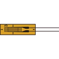
For fillet weld strain measurement, for example, an FLKB‑1‑11 strain gauge can be applied.
Bonding in Regions of High Stress Concentration
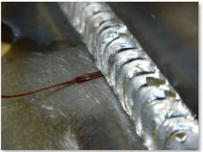
When applying strain gauges on weld beads, the gauge grid must be positioned precisely at the location of highest stress, often near the weld toe transition.
For rounded geometries or pronounced weld beads, using a contour‑matched pressing fixture helps ensure uniform pressure during bonding.
To bring the gauge closer to the target measurement point, the tip of the carrier (base) of the strain gauge may be trimmed. This adjustment does not affect measurement accuracy as long as the measurement remains within the elastic range of the material.
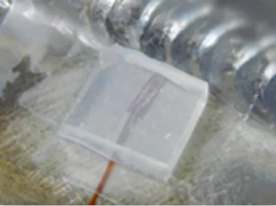
Bonding Strain Gauges on Weld Beads
Since strain gauges require a flat and smooth surface, direct bonding on a pronounced weld bead is usually not possible. In such cases, the bead is carefully ground in the measurement area to create a planar bonding pad.
When preparing the surface, be sure that:
- the structural integrity of the weld is not compromised, and
- the local stress field is not significantly altered.
The strain gauge is then bonded onto the prepared pad.
Matching products
FLKB Series Standard Strain Gauges
- Strain limit: 5% (50000×10⁻⁶ strain)
- 1×10⁶ (±1500×10⁻⁶ strain) Fatigue life
- RoHS2 Directive compliant
Do you have questions about strain gauges?
Need more information about strain gauges or perhaps additional questions or a quotation? Contact our technical experts, who will be happy to help you further.