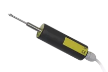
Single point triangulation laser sensors
Modern Laser Triangulation Sensors are suited for precise and safe manufacturing and testing processes. Optical measuring procedures not only help you improve product quality and manufacturing processes, but also cut back on material and energy requirements. The laser triangulation principle lets you make contact-free, rapid, reliable and precise measurements of a wide variety of materials and surfaces.
Your benefit: Even critical surfaces such as hot metals can be measured using our contactless laser triangulation sensors. They use a laser dot to determine the travel, distance, or position of an object (laser distance sensors). These sensors are also used for measuring profiles and clearances. The main characteristics of laser triangulation sensors include:
- Measurement ranges between 2 and 2500 mm
- ±1 µm accuracy
- Sample rates of up to 180 kHz
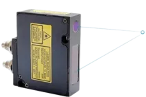
2D/3D laser scanners
2D Laser scanners are used for multidimensional quality controls. They let you create a two- or three-dimensional image of an object. Common applications include profile and contour analyses.
Althen laser distance sensors are based on the widespread red laser. Custom versions using blue lasers are also available. These sensors are particularly suitable for objects with high temperature resistance, as well as mirror and semi-transparent surfaces. We also offer special scanners for welding robots or hole testing:
- Measurement ranges between 10 and 1500 mm
- ±5 µm accuracy
- Sample rates of up to 2000 profiles/s
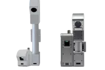
Absolute linear encoders
Do you want to measure or monitor dimensions, roundness, surface profiles, or deformation in technical objects? Use one of our linear encoders. They offer contact-free measurement of linear displacement as an absolute position and are wear- and maintenance-free. The different form factors with high resolutions and rugged construction allow our linear encoders to be used in a wide variety of applications and industries.
The main characteristics of our linear encoders include:
- Innovative technology
- Measurement ranges between 3 and 55 mm
- 1 µm resolution
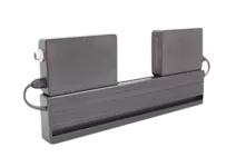
Optical micrometers
Our optical micrometers measure diameters, widths, clearances, segments, or edge lengths of an object based on the “shadow” measurement principle. The system is based on a control and a sensor unit with LED light source, CCD camera, and telecentric lens. First, the laser sensor determines the contours of an object. Then, it calculates the size and position of the object based on the position and size of its shadow. These optical micrometers are often used in manufacturing and quality control. Their main features are:
- Measurement ranges between 5 and 100 mm
- Up to ±0.3 µm accuracy
- Sample rates of up to 10,000 Hz